
Ben Treichel’s Extremely Cool Roaster/Popper Mods
by Ben Treichel--April 2004 All Rights Reserved
Introduction
This article is intended to provide an understanding of what is inside a hot air popcorn popper, and why people perform the modifications they do. I’m not going to provide step-by-step instructions on how to perform the modifications since there are a number of websites’ already on that topic. (http://members.cox.net/felixdial/popper.mods.shtml) Also, I don’t want to have to put a lot of disclaimers in the article like “I’m not telling you to do this” or “ You could electrocute yourself, and burn down your house”, or the always popular, “Don’t try this at Home”. However, YMMV (your mileage may vary).
What’s inside?
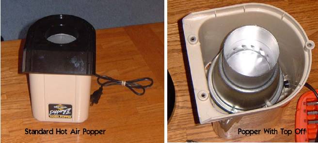
Figure1 shows a ‘standard’ fan and heater pod that is common in poppers like a Poppery II. Fresh Roast products are also similar to these poppers. At the bottom you can see (figure2) a dc fan with a diode bridge.
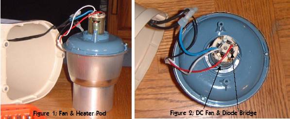
The purpose of the diode bridge (the 4 black things that
form a square) is to convert AC to DC. Before the ac power is sent to the Diode
Bridge, it passes through a secondary heater coil. The purpose of this heater
coil is to provide a voltage drop to the fan. This is required since this is a
12 volt fan motor. Applying the full voltage present at the wall socket will
cause the ‘magic smoke’ to leave the diodes, and destroy the fan.
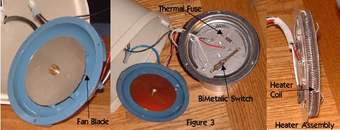
In figure 3 we have opened up the fan and heater pod. At the
left is the fan, with the blades hidden on the underside of the metal disc you
see. To the right in the picture is the heater assembly
.
On top are a ‘thermal fuse’ and a bimetallic switch. The
thermal fuse is designed to fail open too much current is drawn by the heater
coil. The bimetallic switch opens when the heater assembly reaches a specific
temperature (~ 350 F). Both of these are in a popper to act as safety devices;
and you modify or remove these at your own risk. (Ok, maybe one warning.)
If you look in the gap of the heater pod, you can see the main heater coil. What you can’t see is a much smaller coil hidden under the disc, that the thermal fuse and bimetallic switch are mounted on. This is the secondary heater coil that ‘protects’ the fan from being destroyed by being directly connected to the voltage present at the wall.
What isn’t needed.
The bimetallic switch and the thermal fuse are not needed. The secondary heater coil protects the fan from over-voltage, but also slows cooling. The bimetallic switch can be the source of a lot of problems. One of these problems is a stalled roast (temperature never getting high enough). There are several reasons that a roast can stall, one of the most common newbie problems is not enough coffee blocking the airflow to get the air temperature above 400 F. However, the bimetallic switch can also cause this problem. This problem is easily detected by placing a thermometer in the popper and watching the temperature cycle up and down around about the 350-degree range. You might also be able to hear the fan increase in speed when the heater coil turns off. In addition, the bimetallic switch can also disrupt a roast profile by opening during one of your carefully controlled ramps (more on profiling later).
The second item is the thermal fuse. I have found after modifying about a dozen roasters that this fuse will fail sooner or later (without any sort of abuse), and therefore I remove it. However, this is not necessary, and I know a lot of people who would disagree with me on this. This one is really up to the individual.
The final item is the secondary heater. Now I know I told you it protects the fan. However, it also generates heat when you are trying to cool the coffee after you are done roasting. In fact my experience has shown me that without the secondary heater I can cool the coffee to below 200 degrees in less than two minutes. With the heater in the circuit, it takes closer to 3.
So that still leaves the question of how do you protect the fan motor without the secondary coil; more on that in the next section.
Why Split the Fan and Heater?
The most fundamental meaning of splitting the fan and heater is to place a switch into the heater coil circuit. This allows you to turn the heat off at the end of the roast, and allows the fan to continue to run in order to cool the coffee. Also, if you want to start to lengthen your roast from ~ 4 to 6 minutes to 10 or 12, you can also cycle to heater on and off while you are roasting. In fact this is how my PID’ed Poppery controls the heat.
In order to do this manually; you should have a thermometer
like the Marshall or Copper shown on this page. (http://www.sweetmarias.com/prod.roastkits.shtml). This, plus some experience, will improve
your roasts. If you get enough experience with your set-up you can even start
to profile your roasts (Profile – a specific temperature at a specific time).
Earlier I mentioned removing the secondary heater. The
tricks to protecting the fan are either use an AC/DC wall transformer, or buy a
step down transformer. In order to supply DC from a wall transformer you must
remove the Diode Bridge and then wire the transformer directly to the fan
motor. The other option is to buy a step down transformer that will produce AC
in the range of 12 to 18 volts. Remember that we are eliminating the secondary
heater in order to speed cooling time.
The final reason for splitting the fan and heater involves
profiling using a variac.
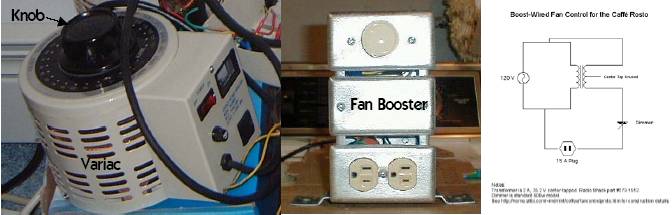
Variacs and Fan Boosting
Variac: A variable AC ‘plug into the wall’ transformer which allows the operator to raise or lower wall voltage from 0 to ~ 130 volts by turning a knob.
Variacs are a common tool of choice for slowing roasts in hot air / fluid bed roasters. They allow continuous use of the heater coil at a reduced wattage level. As soon as I started to use a variac I noticed that it was a bit counter productive when roasting in my Fresh Roast. I had wanted to ‘soften’ the start of the roast so that the beans wouldn’t scorch on starting. However, by reducing the heater voltage; I also reduced the fan voltage. This meant that the temperature of the roast air was still too high. (Temperature is dependent on heater voltage and how fast the fan is running) So I ‘split’ the fan from the heater. By splitting the fan from the heater, this allows the fan to stay at the same speed while the heater voltage is reduced. This means lower air temps and no more scorching.
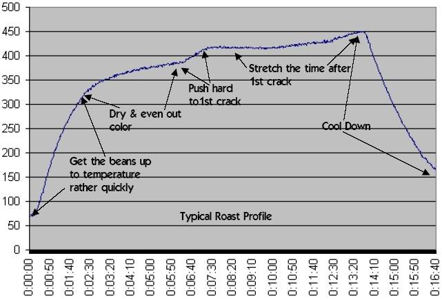
Another aspect of a variac is that with some experience you can learn that “98” (or some other magic value) volts on the variac will cause the beans temperature to go from 300 to 360 degrees in 4 minutes; starting 3 minutes in the roast. Below is an example of profiling a roast and targeting a ramp rate. i.e. 15 degrees per minute.
Fan boosting involves putting more voltage on the fan in order to be able to roast more beans in a single roast. Boosting my Fresh Roast (plus a chamber extender) took me to 4 oz of green. With a PII, I can get 6 oz’s, and in my heavily modified P1, 9 ozs’. Here is a link to the AC version of a fan booster that I use on my P1 (http://mdmint.home.comcast.net/coffee/Rosto_mod.htm). While you are there look around at some of Mikes other projects. Or check out these pages.( http://www.homeroaster.com/intro1.html)
You PID’ed Your Popper?!
Yes. You can see the results below. When I first started profiling with a variac, I started to wonder what effect different ramp rates, etc, would have on the roast quality. However, I was never satisfied with my ability to repeat a roast with sufficient accuracy in order to answer this question.
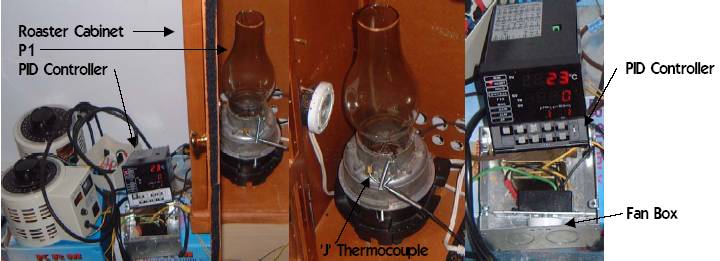
So I knew I needed automation. As a stopgap measure I PID’d my roaster. (The next section will show the depths of my depravity).
Here are the basics on PID's. If you place an on/off switch in your heater coil line, you can decrease the amount of heat going into the roaster. Since heat translates to a specific temperature (based upon a bunch of things) by turning the switch on & off you could control the temperature.
Now since you really want a specific temperature, you
would want a thermometer to read the temperature. Based upon the temperature
readings, you would decide when to turn the switch on and off to achieve the
temperature you wanted. This would allow you to 'profile' your roast. I.e.; @ 10 minutes; 400, 11 minutes; 410,
etc.
Since you are watching and setting a desired temperature based upon time, you are ramping the temperature. This is why we talk about PID's that can ramp. Also, since you are controlling on temperature (temperature being the feedback, heater on time being the input) you are not required to care how heat translates to a specific temperature.
PIDs’ vary from using a variac since with a variac you are reducing the amount of heat that goes into the roaster, instead of turning the heater on and off. However, if you would multiply the time a variac is on, by the number of watts it produces during that time, and do the same to a PID over time, you would achieve the same result. ( i.e. 1000 watts for 60 seconds = 1200 watts for 50 seconds + 0 watts for 10 seconds). However, this equality breaks down in the end if the 'cycle time' of the PID is too long. Cycle time is how often the PID checks to see if it should be on. For a more complete explanation see the link below. http://www.tcnj.edu/~rgraham/PID-tuning.html
Other with issues PID’s that drove me to seek a better solution than a PID controller where;
![]() PID’s were designed to hold a stable
temperature for an oven, or something else much larger than a popper.
PID’s were designed to hold a stable
temperature for an oven, or something else much larger than a popper.
![]() Ramping in PID’s was designed to get
from one temperature to another. (they don’t care about the ramp)
Ramping in PID’s was designed to get
from one temperature to another. (they don’t care about the ramp)
![]() PID’s are designed to be tuned to a
single temperature. Profiling a roast constantly changes temperature.
PID’s are designed to be tuned to a
single temperature. Profiling a roast constantly changes temperature.
![]() PID’s are designed for systems that
don’t change while they are trying to control the temperature.
PID’s are designed for systems that
don’t change while they are trying to control the temperature.
![]() During a roast the beans lose ~ 15% of
their weight, and almost half their density (get larger from roasting). This
also means that more air is moving through the system after 1st
crack than before 1st crack.
During a roast the beans lose ~ 15% of
their weight, and almost half their density (get larger from roasting). This
also means that more air is moving through the system after 1st
crack than before 1st crack.
Insanely Great?!
Or just greatly insane? As I mentioned before, the PID is just a stop gap measure on the road to automation. I working with a group of like minded individuals that are designing a micro-processor control board. FYI, a microprocessor control board. is like the computer that controls your cars engine. This controller is being designed to handle both fluid bed and drum roasters, with either electric or gas heat. Its sized to control anything from a Fresh Roast, to a Diedrich.. I’m not going to name my co-conspirators, I figure they can ‘out’ themselves if they want to. However, you can see some of the project materials here. http://portals.slalomservices.com/DesktopDefault.aspx?tabid=109
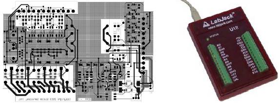
While designing a stand-alone board for roaster control, we
have starting working on the control algorithms using labjacks and PC’s. http://www.labjack.com/ Having PID’ed a
roaster, this allowed us to determine the issues we needed to address in a
roast controller. In order to have control flexibility we have planned on
having 3 or 4 thermocouples in the system. The initial locations of these
thermocouples are before the fan & heater (ambient), before the bean mass
(input temperature), optionally in the bean mass (like my current PID’ed
popper), and after the bean mass. These locations will allow us to determine
both the heat transferred to the bean mass and, the airflow in the system.
Since the controls will be designed for the ramping of
temperatures, we will be able to get good control during the ramps. Also, since
we will control the airflow, we can avoid the problems of changing mass and
density that occurs when using a fluidized bed roaster. Since we will be
controlling on heat transfer and bean temperature, we can accommodate both
electric and gas roasters because we care about the heat going into the beans,
and not wattage, or gas valve position.
 Back to the Main Menu

Ed Needham-Owner
Copyright 1995-2004 © All rights reserved.
Information in this document is subject to change without notice.
This page revised April 13, 2004